Selecting Design Parameters Using a Cost Minimisation Model 3. Selection of Design Parameters for JBPs 2. Planning the biogas plant layout and design ing the digesters, where the rules of thumb for planning the layout of a commercial biog as plant are elucidated and a methodology for specifying the dimensions of both digester(s) and residue storage tank(s) isThe following points highlight the three main parameters used for selecting biogas plant design. The chapter describes the construction steps and operation of biogas plant, which include: a.


A dilution of cow dung with water in the ratio of 1 : 1 is generally preferred.Composition of cattle dung may vary from place to place and thus it is advisable to analyse the TS fraction so that the amount of water to be added to bring the final TS content within 8 to 10 per cent can be determined. Slurry is diluted to optimum level as with higher dilution bigger capacity digester is required. V s represents the volume occupied by the slurry in the digester which can be computed by the relationship-V s (m 3) = Slurry feed rate (m 3/day) x HRT (days)Volume of input slurry for a given quantity of organic wastes depends upon the dilution.
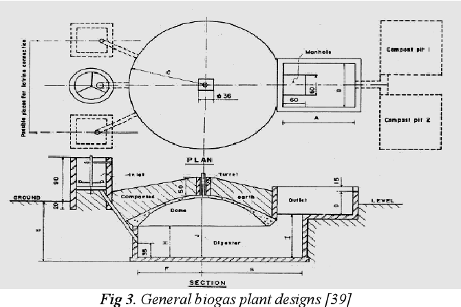
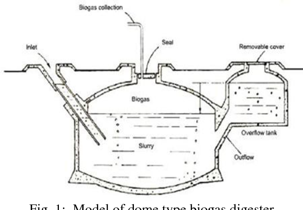
Design of a biogas plant starts from the information concerning availability of wastes per day.Following is the description of various parameters used by TERI for this purpose:W = Weight of animal wastes fed per day (kg/day)V s = Active slurry volume in the digester (m 3)H = Height of the cylindrical portion of the digester upto the top edge of the inlet/outlet opening (lintel), for flat bottom digesters (m)H’ = Same as H, but for curved bottom digesters (m)D = Slurry displacement inside the digester (m)H = Slurry displacement in inlet and outlet tanks (m)Lb = Length and breadth of the inlet and outlet tanks (m)Various design parameters can be estimated with the help of the following relationships:Computation of Slurry Displacements in Inlet and Outlet Tanks:Maximum pressure exerted on gas is equal to the pressure of the water (slurry) column above the lowest slurry level in the inlet and outlet tanks. Thus under ideal operating conditions, volume of slurry flowing out of the digester in a day equals that flowing in. As the compressed gas pushes down the slurry level in the digester, the slurry level in the inlet and outlet tanks rises to a point such that the pressure of the gas is balanced by the pressure of the water column in the inlet and outlet tanks.When the storage space is completely filled with gas, slurry level inside digester is pushed to the lowest position and the slurry level in the inlet and outlet tanks rises to the highest position.Volume of slurry in excess of active digester volume is pushed out through an opening in the outlet tank. Resulting gas from the surface of the slurry accumulates in the space above and gets compressed slightly.
Design Of Biogas Plant Series Of Parameters
H’ is thus computed by the following relationship-The size of the openings in inlet and outlet tanks are normally kept of size 0.5 m 3 x 0.6 m 3 regardless of digester capacity. This, among others, can be solved by iteration.An algebraic solution also exists which is obtained by computing series of parameters as follows:Dome radius is determined with the help of the following relationship-Determination of W for Curved Bottom Digesters:For digesters with curved bottom, the lower base is equal to the upper dome. Substituting this in the above equation, we get-Value of d h can be obtained by solving the above equation which is cubic. For this-Volume of dome which is a part of sphere is given by the following relationship-Recalling that the total volume of gas space is taken as equal to G, V sd as 0.4 G, the remaining gas space volume which is the volume of the dome becomes (G – 0.4 G) or 0.6 G. In this situation, area of the outlet should be doubled to accommodate the slurry displacement. For a case when inlet and outlet tanks have identical shapes, volume of slurry displaced downwards inside the digester is equal to the total volume of slurry displaced upwards in the inlet and outlet tanks.By using the values of h and G obtained earlier, b can be estimated from the above relationship and l can be selected as 1.5 times of b.In some cases, an inlet pipe of 6 to 8 inch diameter is provided instead of inlet tank.
It is to be emphasised that design parameters are by no means ‘optimum’ ones. In India it is customary to express the size or capacity of the plant in terms of designed gas production rate per day whereas in China it is expressed in terms of the volume of the digester.Thus if the capacity is mentioned as 2 m 3 or 70 ft 3, it implies that the plant is designed for producing 2 m 3 (70 ft 3) of gas per day. Concreting whether plain or reinforced should be 4 inch thick.Selection of Design Parameters for 2 m 3 Capacity Plant :For G = 2 m 3, W = 50 kg/day, different parameters can be computed in the following manner:By performing the calculations in the above manner, parameters and dimensions of large capacity plants can similarly be worked out complete summary of which is summarised in Table 5.5. For curved bottoms, two brick layers are provided, the lower layer being 4.5 inch and the upper layer 3 inch thick.
Reddy evolved a cost optimisation model for optimising design parameters of movable drum type biogas plants. Selecting Design Parameters Using a Cost Minimisation Model :D.K. After fixing the design parameters it is also necessary to work out the estimates of items like cement, sand, brick and steel which are used in plant construction.
If r, R s and R r are capital costs of gasholder, its sides and roof respectively, then-Where D is diameter of gasholder, h its height, t its thickness, ρ its density and u its unit cost in Rs/kg (comprising cost of steel, transport, fabrication, welding and painting). In KVIC design, mild steel floating gasholder accounts for nearly 40 per cent of the total cost of biogas plant. This plant has the following dimensions diameter and height of gasholder 6 ft (1.85 m) and 4 ft (1.22 m) respectively and diameter and depth of digester 6.5 ft (1.98 m) and 16 ft (4.88 m) respectively.


 0 kommentar(er)
